
Manual Pick and Place by V.K. Papanikolaou is licensed under a Creative Commons Attribution 4.0 International License.
If you are dealing with tiny SMD parts (e.g. 0402 resistors and capacitors), a manual pick and place machine is a helpful piece of equipment for prototyping and small-batch manufacturing. On the other side, traditional SMD placement using precision tweezers not only requires an ultra-steady hand but also becomes a tiresome drill, especially when working long hours upon fine-pitch PCB footprints.

However, commercial manual pick & place machines are ridiculously expensive ! You have to spend thousands on e.g. this magnificent piece, or even over one thousand for bottom line ones like this.
You would think : Hey, one thousand for a couple of X-Y sliding metal bars ? That was my idea, when started to design my own : total cost ? well under € 100 !

The plans are here in .dxf format (right click - Save As). Grab a free .dxf viewer and check it out. They are pretty self-explanatory : you will need some pieces of MDF, aluminum angles, some bearings and lots of bolts, washers and nuts, all found in your local store. Moreover, you will need a cheap vacuum pen and an small aquarium pump, which has to be reversed in order to work in suction, as explained here. You can even add more extras, like a USB microscope for enhancing the SMD placement precision.

First step is to assemble the base of the machine. No difficulties here; just make sure that the upside-down angles (sliders) are perfectly parallel to each other. A good tip is to make the mounting holes one millimeter (sorry US friends !) larger that the bolt thread diameter, so that it will be easier to make fine adjustments afterwards.

Next step is to prepare the short horizontal slider angles with the addition of bearings, as described in the plans. Here they are, fully assembled :

Now attach them to the underside of the horizontal tray with using wood screws and washers. Be careful : use only four screws per slider and tight it up from their sides. Place the tray on the base before tightening fully; make sure that the tray slides freely and all eight bearings are touching the bottom sliders at the same time (you can still readjust the base sliders as well). Now you have a fully working horizontal tray (x-axis) !


Next step is to prepare the pen holder slider as described in the plans. The pen holder slides on the horizontal tray (y-axis) by using eight bearings and two aluminum angles mounted on the tray, mirrored to each other (thanks to this guy for sharing his idea). If your bearings are not touching both angles at the first time don't worry; use two large washers to uplift one of the angles and then make necessary fine adjustments. With a bit of patience, the pen slider will work flawlessly without any jitter.


Now you are ready to place the vacuum pen vertically on its dedicated slider (z-axis). I used two needle bearings (12 mm inner diameter) mounted on the slider by two U-bolts, as shown in the picture. I also used a longer 12 mm tube for the pen, salvaging only the tip and the tail from the cheap manual button-pen I bought from eBay. I also used one U-bolt to mount a USB microscope (at a small angle) next to the vacuum pen. However, you can always use your imagination for alternative configurations (and please share them) !

The last bit : destroy a notepad (a real one !) and get the wire. This kind of wire is excellent for making a short compression spring for the vacuum pen. Wind the wire around the pen tube and it is ready in seconds ! Insert the spring in the tube and secure it at the top with an elastic band (or whatever you may think of), while its bottom sits on the needle bearing. A couple of sewing-machine-oil drops inside the needle bearings is always a good idea. Leave a clearence of about an inch (for my US friends) between the base and the needle tip and your manual pick & place machine is READY !


Now you can pick up your fine SMD components by moving both the tray and pen slider (X-Y) with your arm and lowering the pen with your hand (Z), while activating the vacuum pump (I made a foot switch for this). You already noticed that, thanks to the needle bearings, the pen can rotate around its axis as well, in order to perfectly align the picked component. Max working area 400x200 mm (too much for anything !).
A nice detail for the end - little slots for vacuum pen tips. I am thinking of adding more upgrades in the future, but I've run out of ideas - please send me yours !


Now you can pick up your fine SMD components by moving both the tray and pen slider (X-Y) with your arm and lowering the pen with your hand (Z), while activating the vacuum pump (I made a foot switch for this). You already noticed that, thanks to the needle bearings, the pen can rotate around its axis as well, in order to perfectly align the picked component. Max working area 400x200 mm (too much for anything !).
From my first experience, this machine is VERY accurate ! Hence, I am encouraging you to go for it.
A nice detail for the end - little slots for vacuum pen tips. I am thinking of adding more upgrades in the future, but I've run out of ideas - please send me yours !

Update : since the MDF has tiny spots that may distract vision from small SMD components (e.g. 0402), a nice idea is to apply a white paint coating (matte, not glossy) over the pen usable area :

Here's some views from the USB microscope that is attached next to the vacuum pen. It also features adjustable LED lighting.


Update 2 : found this little gem (memory foam) in eBay for £1 ! It really feels great and looks cool :

And finally, the HD action video is here !
(a big thanks to my friend George for his help on precise wood/metal drilling)
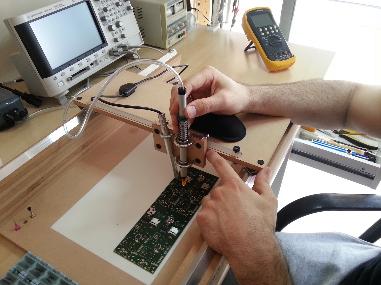
Update 3 (14/05/13) : after placing some hundreds of small 0402 components, I have developed a good technique for better pen stability : I hold the pen with my right hand and I use my left hand to 'lock' the tray into place as shown in the picture below.

Nice job! I'd love to see a video of it in action.
ReplyDeletewill be shot and uploaded as soon as I get my new PCBs from factory. thanks :)
DeleteGreat work! Are you working on video please?
ReplyDeleteThanks a lot ! Please be patient, I am waiting for some PCBs to arrive from the factory to show the real thing !
DeleteWow, nice work. Want to see pictures from the USB Cam.
ReplyDeleteadded ! thanks !
DeleteI love it! so simple and nice construction.
ReplyDeletethanks a very lot :)
DeleteThis may be a little overkill, but adding motors and a joystick would be awesome. lol
ReplyDeleteOverkill?? Not at all. Adding motors and some form of manual control (I like jog wheels) is the next logical step for a high-precision pick and place aid.
DeleteCould you theoretically hack two inkjet printers to automatically pick and place components sort of assembly-line-like?
ReplyDeletewould be nice to add a pair of stepper motors...
ReplyDeleteI think this is great. Ingenuity at work. If you're only doing a few PCBs occasionally and applying just a few SMD parts, this is an ideal solution.
ReplyDeleteThanks for sharing.
Mike
Thanks a lot for your nice words :)
DeleteYes! Watching the full PCB assembly demo in the other video was a revelation to me. A system like this changes what level of SMD building is possible at home with modest equipment. Great work!!
Deletejust curious, what usb microscope did you use?
ReplyDeletethanks for asking, I just put a link in the respective text.
DeleteI don't understand the purpose of this machine. I understand that you might want to pick up and place small items, but the ones in the pictures are big enough to handle manually.
ReplyDelete0402 parts are 0.04" long ...
Deletehttp://en.wikipedia.org/wiki/File:SMT_sizes,_based_on_original_by_Zureks.svg
DeleteSo it is better to have good rotation of the vacuum pen than good vertical motion? I would have used linear bearings like the LM12UU. Is there a particular reason you used the needle bearing over a linear one?
ReplyDeleteyes, only one : cost :)
Deletelinear bearings are of course better but they are a bit expensive.
On second thought, it may worth the extra cost. Thanks for pointing this out !
Deletejust ordered :)
DeleteWell, just tried the LM12UUs. Unfortunately, I found them rather bulky and heavy, but most importantly, the rotation they provide is horrible. They are slightly more stable than needle bearings, but without smooth rotation they are not very practical. Hence, I'd rather stick with the needle bearing solution (excellent rotation and very satisfactory vertical movement).
Deletejust built machine - thanks . The X Y are so smooth that any arm movement is translated to needle head so I battle to have stability on the release and often jiggle the part . Any ideas on mechanical damping or gearing ie 5 degree arm translates to 1 degree pin movement . At present any movement of x-y is 1/1 translation .
Deletethanks again for your design .
why don't you just wire a stepper motor to the Y axis and wire it to a joystick, or better yet, integrate an arduino or something to power it based on 2 key presses?
DeleteAbsolutely great! I'm definitely building one. Thanks a lot for inspiration!
ReplyDeletei love it, great idea for sliders :)
ReplyDeleteUn Cappo!!! Flicitaciones y muchas gracias por compartir
ReplyDeletecongrats. i will be building one soon!
ReplyDeleteHi,
ReplyDeleteWe will use rollerblade bearings. It's small and lowcost.
Thanks
Nice, and if you made a kit of needed parts, I would buy it :)
ReplyDeleteI was going to build one then I found this on ebay. Had it for a few weeks now and it's awesome.
Deletehttp://www.ebay.com/itm/SteadyHands-PNP-Manual-SMD-SMT-Pick-and-Place-with-Vacuum-/191120482395
Made comment on wrong page... I like it and I plan on making one. How did you make the foot controls tho? Saw instructions for converting aquarium pump but nothing on the controls.
ReplyDeleteThere's nothing special about it, just a switch to give power to the pump. You can use any ready foot switch or build your own. I just mounted a large button switch on a plastic box and works fine.
ReplyDeleteGreat post, thanks for all the info.
ReplyDeleteWhere did you get the vacuum pen tips? The one on Ebay goes to 1.5mm - is this small enough for smaller SMT parts?
Thanks again.
Suggested .dxf viewer gave me trouble but I found an online file converter that spit out a .png image of the file with, I think, everything I needed.
ReplyDeleteGot a couple questions.
ReplyDelete1. How did you get the holes drilled on the rails? I don't have a drill press at my disposal.
2. How thick is the MDF supposed to be? I looked at the schematic and it says something about t=10 or t=12 which I'm no absoltuely sure of the meaning of. I figured it meant 10 mm thickness and since my MDF is 20mm thick I've only cut 3 wall pieces for each side so far.
Thanks!
I used a drill press, but if you have a steady hand, usual drilling against a hard wooden surface will do.
DeleteAt my local store, there were 10,12,16,20 and 25 mm MDF sheets. I think it would be difficult to build it with 20 mm thick MDF.
Yes, as far as the wall sides are concerned, 3x20mm parts will do even better.
DeleteThanks!
DeleteI'm using your design as a stepping stone on my way to (I hope) some CNC machines, but first I needed to learn to build the 2 axis rail system.
Since I want to do surface mount in the future anyway, this is a good investment and learning experience.
Very nice work!
ReplyDeletei will like to ask you where i can buy nazzle like pink and orange you have, i tray to find on ebay but i cant.
thanks
Check this : http://www.ebay.com/itm/Needle-Dispensing-Dispenser-Bottle-for-Rosin-Solder-Flux-Paste-9-Needles-50ml-/261149950583?pt=LH_DefaultDomain_0&hash=item3ccdc00277
DeleteIt's all fun and games, until you suck an 0201 component up into your vacuum:) haha j/k . This is fantastic, and beats paying 3000+ for a machine. The machine may be automatic, but this is just what someone who does occasional SMD boards needs to speed stuff up. Only reason I use 0603 and larger is because 0402 is really hard to hold steady.
ReplyDeleteFantastic job making this!
With 0603 parts, placing with this machine gets very easy.
DeleteThe most difficult part is the 0402 capacitor !
Perhaps a small bit of mesh on the top of the pen covering the vacuum intake would save the day?
Deletewhat is keeping the usb microscope from falling down?
ReplyDeleteI'm curious as to how much you use the USB microscope for placement and how much you place by eye. Thanks
ReplyDeletethanks for your inspiration :)
ReplyDeletethis my Pick & Place
http://www.youtube.com/watch?v=7izx6NG1hhA&feature=share
Nice work....
ReplyDeletegoing to make an excat replica... but i have trouble sourcing the parts... spec the alu angles and ubolts... where did you get your parts?
think i also found some errors in the plan:
ReplyDeleteyou say 10*(M3*30) i can only find 6 on the drawing... maybe you counted the 4 threaded rod in to the number?
close conected to above... you say 2*(threaded rod M5*100) but i count 4, one at each end of the 2 walls or one in each corner if you will
you forgot all the nuts:
22*M3
14*M5
8*M6
and some washers for the ubolts so the wood is not crushed
8*M6
for under the long alu angles (one in each end of bolt)
12*M3
same for the 4 rods
8*M5
for the short alu angles
4*M6
for the 4 bolts that holds the bearings on the holder for pick&place and microscope
8*M3
The link with dxf file doesn't work anymore. Can you upload it again please? Thx!
ReplyDeleteThis is a wonderful post. Just the thing to overcome the unsteadiness of my hands. However, I'm having trouble downloading the .dxf file. Could I trouble you to check the link. Thank you.
ReplyDeleteI cannot bring the plans up I don't have windows 7 or 8 which is what your suggested viewer requires. What are the cut out dimensions of the MDF panels?
ReplyDeleteIs the dxf link no good anymore? I have tried opening in solidworks and abveiwer, all I get is error messages.
ReplyDeleteWhich brand/model Pick Place Vacuum Pen do you use? I couldn't find a good one.
ReplyDeleteThanks,
I need to know the bearing sizes for the vacuum pen you used. My computer will not allow me to save the dxf. file and I'm having trouble with that part.
ReplyDeleteright-click on dxf link -> save link as
ReplyDeleteVery interesting. Now I'm trying to think of how I could modify it to add detentes/notches every 90° to the nozzle.
ReplyDeleteI usually have far too many components to place them loose, so I always pull directly from the strips. If I place the board square, and have a channel to keep the strip aligned square, adding detentes should keep everything aligned at 90°. Then I just need to align X & Y when placing parts.
Hello and thanks for sharing. Unfortunately seems that the DXF file is not available anymore :(.
ReplyDeletePlease anyone can send it to me at amigamerlin_nospam@gmail.com (please remove _nospam) from email address.
Thank you you all
I know it's been two years since you released this but are the DXF plans still available?
ReplyDeleteThe link in the article no longer works.
Are the DXF plans still available for download?
ReplyDeleteLink in article no longer works.
I used a vacuum pump for the longest time. Then one day my foot switch broke and I was in a hurry so I just put the tube in my mouth. It was so much easier than the foot switch and waiting for vacuum pressure to fall that I have use my mouth ever since.
ReplyDeleteI want this machine can pay for it can you please give a reference how can i get it please
ReplyDeleteMy name is Mr.Hitesh
+919711290069
At first sight, it looked to me not interesting. Later I thought this could be useful for non firm pulse people haha, but later I thought, this has so much potential adding some cnc controls ... Any upgrade since 2012? Greetings and sorry if I wrote something wrong, english is not my first language.
ReplyDeleteExcellent job
ReplyDeleteAnd a couple of months later, I'm very interested in this machine, I've been looking for information about other version of this one and I would suggest to add some electromagnets (pedal controlled) to stuck X and Y axis.
ReplyDeleteI wondered how difficult it would be to add a foot pedal to lock both carriers on their rails? My best guess: use one of these small rubber air blowers (used to clean lenses). Add hard wall tubing to the carriers (aquarium gear), and a shorter piece of soft latex tubing just along the carrier. So when you step on the blower the softer pieces of tubing expands. Make it lock gently the carrier by friction between the carrier and some static structure or rail (or add a small alu extrusion along the rail at the adequate distance). My two cents :)
ReplyDeleteDear vpapanic. Thank you for the great idea. I've just finished my pnp machine and really happy for the results. My pnp is slightly different, but without seeing yours, I would not even tried to make one. https://youtu.be/LftkSK-TZ8U
ReplyDeleteHow many components per hour on average can you place?
ReplyDeleteHello
ReplyDeletePlease can you give some information to construct this kind of machine, pick and place?
If you have a material list and a drawing with measurements how to build the machine.
Thank you very much
Kind regards
Helmut
First of all I would like to say Thank You for taking the time to share this information. I discovered this site about a year ago and said that before I built my next board I would build this unit. Took a couple of weeks but that was because some sections I ended up doing several times until I was happy with the result. Since I'm in the U.S. I had to translate the dimensions anyway, so I really started with the overall concept and went from there. I discovered that the best place to get the ball bearings was Amazon.com - you can get a package of 10 of them for about $10. The wood and aluminum angles came from Lowes (a Home Improvement chain here in the U.S). The major areas where I deviated from the original design were in the vacuum pen and vacuum pen holder. Your holder was done with wood where I did mine in aluminum flat bar (also from Lowes). I found that this was a bit easier to align once it was built. As for the vacuum pen, we have a lot of hobby stores here in the U.S. and many of them carry parts for radio controlled aircraft. One of the things that those folks use is small brass tubing and there is a company (ksmetals.com) that makes a number of different sizes. I used their #8128 (5/32" OD) and #8129 (3/16" OD) and found that the smaller one fit perfectly inside the larger one allowing vertical and rotational movement with very little "wiggle room". Further, the dispensing syringe tips that are perfect for the tip on the vacuum fit perfectly over the smaller brass tubing. For a vacuum, I used an aquarium pump (there are a number of sites online that show how to easily convert these from pump to vacuum) and the plastic tubing was only slightly larger than the OD of the larger tubing. A small piece of heat shrink tubing made a great air tight seal on that end. The other major change was the camera. I've used the "USB endoscope" cameras before and was not all that happy with them. I opted for using a Raspberry Pi with a camera module (available from Adafruit.com). This provides 1080p resolution at 30 fps in color. Further, the camera focus is mechanically adjustable (comes with an adjustment tool) and the software provides digital zoom so that I can easily align the area of interest to the center of the screen and zoom in to where it looks great. Another nice thing about the small diameter of the vacuum pen is that it allows the camera to be mounted closer to the pen providing a more vertical view and less angular distortion. The downside of this approach is that it is more difficult to determine the height above the board. I solved this by using a white LED mounted on the vertical pen holder assembly which shines where the part will be mounted on the board. This provides a shadow (in my case) to the left of the part that gets smaller as the part decends towards the board.
ReplyDeleteAll in all, I am extremely happy with the way things turned out. I have built two boards now and both came out much better than anything I ever did by hand and took far less time to do it. Again, many thanks for providing the inspiration for this.
Dave Harper
I"ve made one for myself, inspired form your machine. :)
ReplyDeletehttps://blog.jayvee-store.com/2017/06/26/manual-pick-and-place-machine/
I've made some changes I think it's easier for me such as the drilling, press-switch.
Woooha.... Sooooooppper
ReplyDeleteWow I've just made one of these and it works nicely. Thinking about making a kit up of there is some interest. Not sure how that works for you Vpapanik? Basically collect up the components apart from the MDF which can be sourced locally.
ReplyDeleteMake a kit and I may consider buying it if the price is right. My budget is less than $200USD and I'm in the U.S. Reply here if that works for you.
DeleteWhich vacuum pen is this? Can't find it anymore. Length and diameter would be nice to know. Maybe the manufacturer?
ReplyDelete